- By - Malfaifi
- Posted on
- Posted in التركيبات, التركيبات الثابتة
Ferrule Design
Sorensen 1990
Ferrule design and fracture resistance of endodontically treated teeth
Sorensen et al 1990
The term coined by Eissman, and he recommends to be 2 mm.
To exam the effect of various ferrle designs on fracture resistance of endodontically treated anterior teeth.
Material and methods
1) 60 intact maxillary central incisors were randomly assigned to 6 groups
2) The teeth were decoronated: Group 1 and 2- 15mm, group 3 to 6 – 17mm
3) Endodontic therapy: No 45 file and No.50 file, Filling No.40 GP cone with plugger and lateral filling
4) Prep teeth according to the guideline
5) Coronal tooth structure was measured at the point indicated and the width of the root was recorded at several level.
6) The length of the prepared canal was confirmed and a plastic #4 Parapost which is same as the crown length.
7) A preformed anterior core pattern #1 was adjusted to contact the proximal surface and 7mm in length from the facial margin to the incisal edge. After complete polymerization, the core was prepared to 1.5mm axial reduction.
8) Cast with Silver palladium metal and cement the post w/ ZPC. Remove the excess cement in static loading machine for 15min with 2.72kg of pressure.
9) Fabricate the crown using 3M size 15 polycarbonate crown and wax. Cast the crown with base metal alloy and cement it with ZPC.
10) Took a radiograph and measure the width of the labial and lingual tooth structure.
11) The teeth were embedded in autopolymerizing acrylic resin.
12) Applied controlled loads to the teeth at a crosshead speed of 2.54mm/min at an angle of 130 degree to its long axis.
|
Group |
Designs |
|
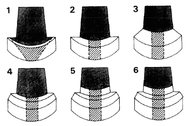
1 |
90 degree shoulder, no coronal dentinal extension maintaining 1mm of axial tooth structure at the shoulder |
|
2 |
90 degree shoulder without coronal dentinal extension |
|
3 |
130 degree angle forming a sloped shoulder from the base of the core to margin, all tooth structure above the axial gingival line angle was removed |
|
4 |
90 degree shoulder, 1mm wide 60 degree bevel finish line with no coronal dentinal extension |
|
5 |
90 degree shoulder, 1 mm wide 60 degree bevel finish line, 1mm coronal dentinal extension. A butt-joint at the tooth core junction |
|
6 |
90 degree shoulder, 1mm wide 60 degree bevel finish line and 2 mm coronal dentinal extension. 1mm wide 60 degree contrabevel at tooth core junction |
The amount of residual axial tooth structure at the crown margin was found not significant in resisting fracture. There was no difference in the failure threshold between groups 1 and 2.
Group 3 had the ferrule effect at two level,
1) between the core and the residual tooth structure of the sloped shoulder
2) between the crown and the margin. This design did not contribute to fracture resistance or failure thresholds despite popular clinical guideline.
Group 2 had a shoulder prep. and group 4 had a shoulder bevel margin, but the mode of failure and failure threshold was equal for both groups.
Group 4 and 5 had identical crown margins but group 5 had 1mm of residual dentin coronal to the shoulder of the margin prep. In the evaluation of failure thresholds, group 5 exhibited nearly double the failure threshold of group 4. From the present study, the critical design of the tooth prep is an extension of at least 1mm of coronal dentin above the shoulder of the prep.
Group 6 differed from group 5 by an additional 1mm height with a contrabevel at the junction of the core and tooth. However, the failure thresholds were not significantly different between groups 5 and 6. Therefore, a contrabevel did not increase fracture resistance.
The ferrule is defined as an encircling band of cast metal. This study demonstrated that it was not the contrabevel or metal collar of the cast core, but the resistance form of the artificial crown against the residual coronal dentin that is crucial in the design. The ferrule is provided by parallel walls of dentin coronal to the shoulder of the preparation that elevates resistance form. So the ferrule effect is a 360 degree metal collar of the crown surrounding the parallel walls of the dentin extending coronal to the shoulder of the preparation.
Conclusion
1. 1mm of coronal dentin above the shoulder significantly increased the failure threshold.
2. The preparation of the coronal walls should be parallel for maximum resistance form.
3. The contrabevel design at either the tooth-core junction or the crown margin did not improve the failure threshold.
4. The axial width of the tooth at the crown margin did not significantly increase the fracture resistance or alter the failure threshold.